Active Monopole Preamplifier
I was thinking about building a high input impedance amplifier to connect between a short vertical monopole and a spectrum analyzer or software defined radio (SDR) as an addition to my laboratory. I had seen these amplifiers in several RF compliance laboratories and they were occasionally used to measure vertically polarized field strength in the HF radio spectrum even though most regulations require that HF range frequency emissions be measured via conducted measurements. I obtained a schematic for one years ago and was surprised that the amplifier had a voltage gain of less than unity. This didn't seem reasonable but maybe it would work for laboratory use. I thought that having one would be fun to play but I never did anything about getting one.
What is this and why might I want one?
A couple of years ago I got involved with helping a ham who had a big interference problem on the upper end of 80m. Click here for a webpage on this website for the details. In the process of tracking this interference I decided that I now had a reason to build a circuit to look at a wide chunk of RF spectrum which could be connected to either a portable spectrum analyzer or an SDR. Web searches brought up several documents by Dallas Lankford and Chris Trask, N7ZWY from 2007-2008 discussing this very topic. These amplifiers all had voltage gain less than unity and were for non-laboratory use. I appreciate their prior work as it helped my design considerably.
A short vertical has a source impedance that is capacitive, in the order of 5-20pF, and is capable of capturing a voltage that is about one half of the E-field strength over the length of the antenna. This assumes that the circuit connected to the vertical does not load down its driving impedance. A circuit with 5pF to ground will lose 1/3 of the available voltage for an antenna with a source impedance of 10pF. Therefore the amplifier must be designed carefully.
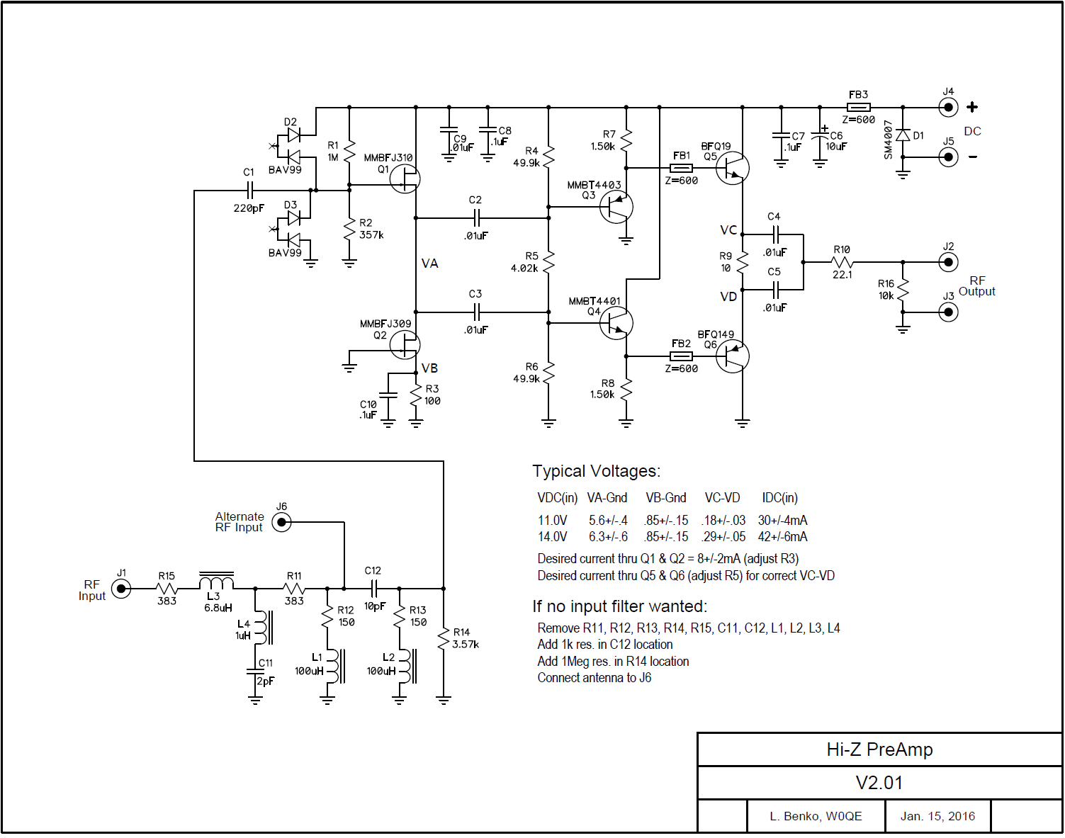
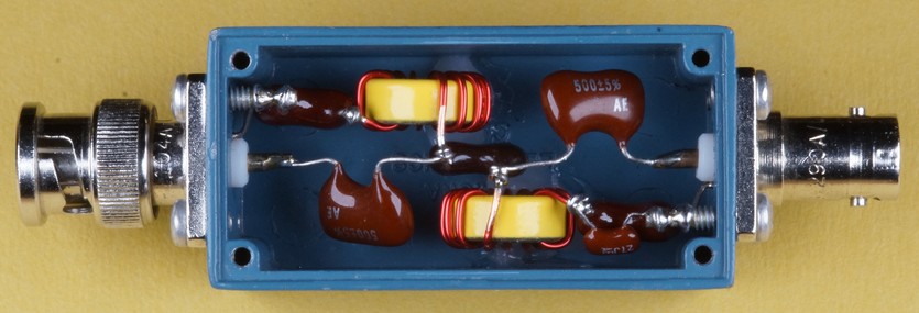
The final circuit is shown below.
A short vertical has a source impedance that is capacitive, in the order of 5-20pF, and is capable of capturing a voltage that is about one half of the E-field strength over the length of the antenna. This assumes that the circuit connected to the vertical does not load down its driving impedance. A circuit with 5pF to ground will lose 1/3 of the available voltage for an antenna with a source impedance of 10pF. Therefore the amplifier must be designed carefully.
The final circuit is shown below.
Fast Forward 10 Years
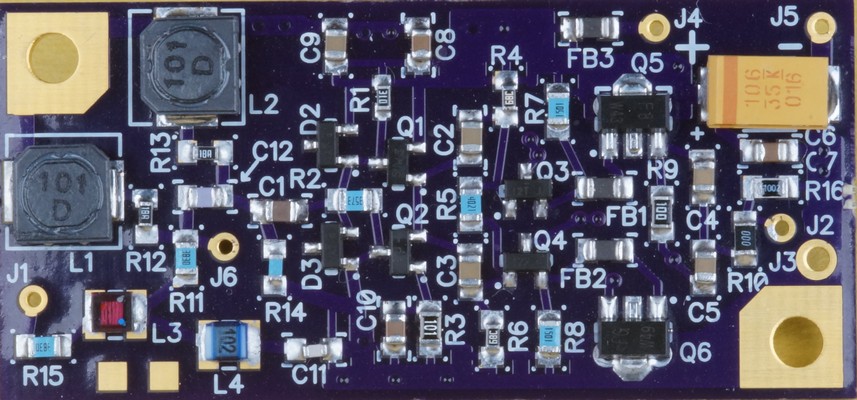
After a few iterations to the circuit a small 1" x 2" double sided printed circuit board (PCB) was laid out and fabbed. The components are mostly 0805 and the small transistors and diodes are SOT-23.
It is fun and yet seriously depressing to drive around and see all the "unintentional radiators" throughout the entire HF spectrum.
This project is divided into 3 parts:
This page is the active monopole amplifier.
The RF clipper is here.
Spectrum display RF tracking is here.
If you are interested in more information:
High resolution pictures, schematic, and bill of materials (BOM) click here. You can right click and save as.
Also the PCB layout has been made freely available on the Oskpark website. A link to the PCB layout is here and 3 ENIG gold plated printed circuit boards will cost you ~$10 delivered to your mailbox in about 10 days. Oshpark (www.oshpark.com) is located in Oregon and is a great place to have small quantities of PCBs made.
To order 3 PCBs click here.
There are several ways to measure the performance of an amplifier including intermodulation distortion (IMD), signal to noise ratio, total harmonic distortion etc. I decided to measure the harmonics produced by the amplifier at various input levels which turned out to be quite involved. The following drawing shows what I did.
Laboratory Performance
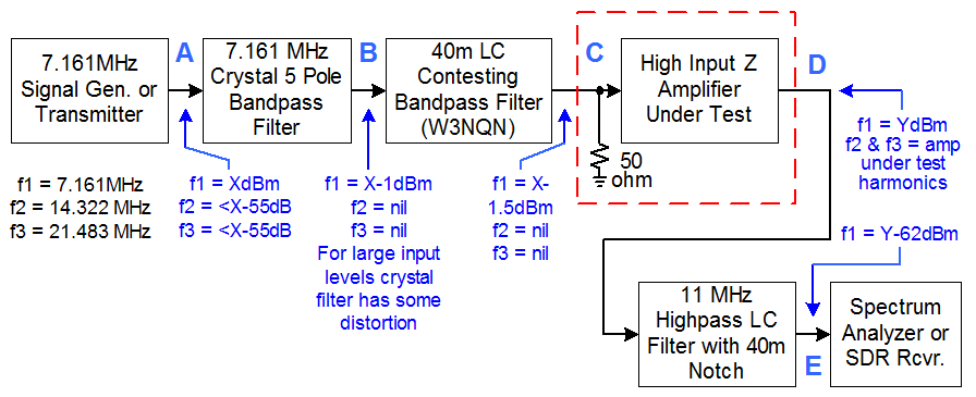
I needed an ultra clean driving signal with harmonics down at least 120dB. My signal generators had harmonic suppression of 55-60dB which was not even close to what I needed. I decided to drive the amplifier with a 40m signal and look at the harmonics on 20m (2nd harmonic) and 15m (3rd harmonic). I took the signal generator output and ran it through a homemade 5 pole crystal bandpass filter centered at 7.161MHz. This reduced the harmonics to less than 120dB for low and medium level inputs. For high level inputs the crystal filter had some small distortion so I followed this filter with an LC bandpass filter which passed the 7.161MHz signal and had 70dB of attenuation at 14MHz and 45dB at 21 MHz. Now I had a very pure 7MHz signal but didn't have any equipment to measure this dynamic range.
Therefore I needed better equipment or some way to allow my existing gear to be able to do the measurements. The 11 MHz Highpass filter with a 7.0-7.3MHz notch in the above drawing and pictured below reduces the 7MHz fundamental frequency by more than 60dB allowing my existing equipment to easily make harmonic measurements that are down 120dB. If interested, the design of this filter is chronicled in a YouTube video and can be watched by clicking here.
The filter specs were: 7.0-7.3MHz <-60dB, 14.2MHz = -.16dB, 21.4MHz = -.08dB and is shown below.
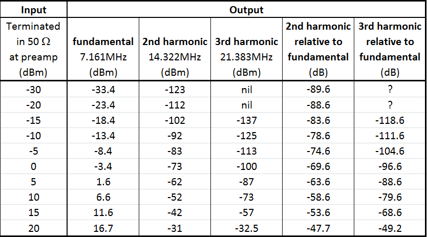
The following table shows the average performance for 6 amplifiers that I built.
I intended to use this amplifier to drive a Perseus SDR which begins clipping at -2dBm. At the clipping level of the Perseus the amplifier has the 2nd harmonic down 72dB and the 3rd harmonic down 99dB relative to the fundamental which is quite good. However this performance comes with an amplifier which is capable of an output level of nearly +25dBm which can easily damage some receivers. If this a a potential issue for you I built an RF clipper to protect the SDR. Click here to see the clipper project and its performance.
Performance in the Field
I built 3 preamps with AM/FM filters capable with a passband of 2.7MHz to 30MHz and 3 preamps with no filter with a passband from 300kHz to 55MHz.
I live 8.0 miles from a 50kW (daytime) AM radio station (KDSP 760kHz) and have a line of sight to the towers. During the day form my driveway the 760kHz signal is -3dBm after the amplifier which is right a the verge of clipping on the Perseus. Driving to the transmitter sight and parking within 300 ft. of the towers produces a signal level using the amplifier with the filter of -32dBm and I can hear signals on all the ham bands without any interference from the nearby transmitter. The amplifier without the filter is totally crushed in this case but is not damaged. The filter provides 61dB of attenuation at 760KHz so the amplifier sees a signal that should produce a signal of +29dBm out if it didn't poop out.
I live 8.0 miles from a 50kW (daytime) AM radio station (KDSP 760kHz) and have a line of sight to the towers. During the day form my driveway the 760kHz signal is -3dBm after the amplifier which is right a the verge of clipping on the Perseus. Driving to the transmitter sight and parking within 300 ft. of the towers produces a signal level using the amplifier with the filter of -32dBm and I can hear signals on all the ham bands without any interference from the nearby transmitter. The amplifier without the filter is totally crushed in this case but is not damaged. The filter provides 61dB of attenuation at 760KHz so the amplifier sees a signal that should produce a signal of +29dBm out if it didn't poop out.
Finished Amplifier
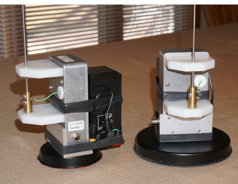
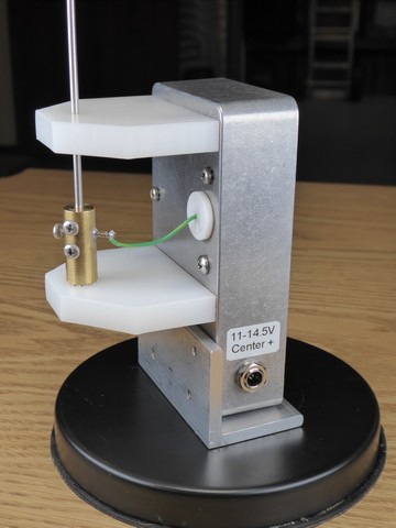
The picture below shows 2 of the final amplifiers that I built. One has a 3.5" magnet base and the other has a 5" base with a heavy rubber bottom which helps in not damaging the surface finish of the vehicle and also because the magnet is really too strong for such a light antenna. The 3.5" mag mount is an MFJ-333BS or MFJ33BM with the supplied connector or thread removed. Also the supplied coax is discarded. The 3.5" mag mount is adequate at 70MPH on the highway. The 5" mag mount is also from MFJ. A right angle piece of aluminum mounts the box to existing holes in the mag mount.
The diecast box is mounted to the right angle piece of aluminum and is a Hammond 1590 series box that is 4.48"x2.29"x1.06". The small 12V 2Ah gel cell is connected to the diecast box with black rubber bands and can power the amplifier for more than a day of continuous use. This aleviates phanton powering the the DC voltage on the coax and the voltage supplied from the cel cell is extremely RF quiet. The the 48" long stainless steel whip antennas are tapered from .100" diameter at the base to .063" at the top resulting in a very stealthy setup.
The large white HDPE plastic standoffs and feed thru are to minimize the antenna capacitance to ground which reduces the antenna signal available to the amplifier. HDPE (high density polyethylene) is used since it is cheap, machines well, and most importantly has a low dielectric constant (2.1) which helps minimize the capacitance. Most plastics such as delrin, polycarbonate, ABS, PVC etc. have dielectric constants >3.4. I don't plan to use this setup in the rain (since it hardly ever rains in Colorado) but if it does the green wire from the antenna has a small dip in it acting as a drip catcher. Variants of the diecastt box can be had with a weatherproof gasket. Then a piece of PVC tape could shield the BNC and the DC barrell from the rain if desired.
Conclusion
Page content last updated Feb. 4, 2017
Copyright © 2017 Larry Benko, W0QE
How Well Does It Hear?
A mobile or portable device that is used to track RFI needs to be able to hear the same offending noise that you hear with a much larger antenna. I was skeptical about this happening but was pleasantly surprised. Fundamentally if the noise that is received does not significantly increase when the antenna is connected then you are not able to hear all the signals that you should be able to. However if you live in a very noise location you still can't hear all the signals. So the goal is to go to the quietest location possible and see that the noise significantly increases when the antenna is connected.
Hopefully this makes sense! If my "XYZ" antenna causes a 20dB noise increase in my receiver when connected and my "ABC" antenna causes a 10dB noise increase when connented then both antennas will hear the same signals. The antenna witht he 20dB noise increase will hear the weakest signals with a slightly better signal to noise ratio but generally you are looking for noise that is not that weak. The noise level received is a function of receiver bandwidth so using a narrow bandwidth is analagous to going to a quiet location.
I took a 100 mile daytime drive with the active monoploe amplifier and the Perseus SDR and listened on 40m with a resolution bandwidth of 500Hz. I tuned around 7.1 - 7.15MHz always looking for an area with no signals that had a signature as I was looking for the base noise level.
The following readings were observed with a 500Hz resolution bandwidth:
My (W0QE) driveway = -108dBm
W0IVJ's driveway = -102dBm
K0DK's driveway = -117dBm
The noisiest location found = -76dBm
The quietest location = -119dBm (no houses, no power lines, no line of sight to populated areas)
Using K0DK's location has the quietest location with a comparison antenna I made some measurements:
Perseus + RF clipper connected to a 50 ohm termination,
500Hz RBW (base Perseus noise level) = -127.3dBm
Perseus + RF clipper connected to powered active monopole amplifier with filter and NO whip antenna
500 Hz RBW = -123.9dBm
Perseus + RF clipper connected to powered active monopole amplifier without filter and NO whip antenna
500Hz RBW = -124.2dBm
Perseus + RF clipper connected to powered active monopole amplifier with filter and with whip antenna
500Hz RBW = -117dBm
Perseus with RF clipper connected to K0DK's 100 ft. high dipole, 500Hz RBW = -106dBm
Takeaways:
1.) Connecting the whip antenna to the active monopole amplifier increased the received noise by 7dB when done at an incredibly quiet location. The increase would have been larger at a noisy location.
2.) The sensitivity of the active monopole amplifier with a 4' whip is 11dB below a high full sized 40m dipole. However one is vertically polarized and the other is horizontally polarized.
K0DK told me that he had some suspected powerline noise that he was hearing at about S3 on 20m. He has stacked 4 element yagis and had figured out the bearing. We went out to my vehicle and I could also hear the power line noise with the active monopole amplifier and we were able to drive directly to the closest place to the pole without having to get out and walk the remainder.