RF Signal Strength Measurements
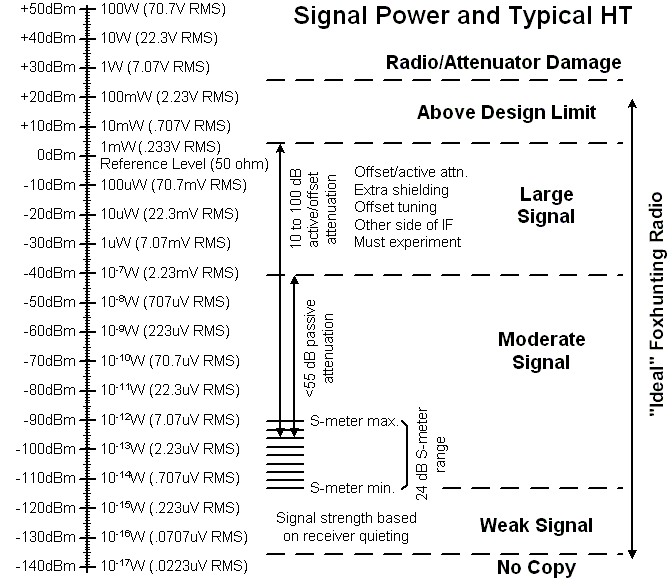
RF signal strengths vary over a range that is very difficult to comprehend. Therefore it is much easier to refer to signal strengths in a logarithmic space. Usually a power level of 1 mW (milliwatt) is defined as the base level and all signals are relative to that level. A "Bel" is a 10 times increase in power and a decibel (dB) is 1/10 of a Bel. Units of RF power are usually expressed in dB. relative to a base or dBm. (dB relative to 1 milliwatt normally in a 50 ohm system). The chart below shows a lot of information but the scale on the left goes from -140dBm which is about the weakest signal that a radio can receive to +50dBm which is 100 watts.
How close can you get?
Assuming a setup where any signal larger than -30dBm to the attenuator input causes the receiver to no longer show proper receive levels and you are using a 3 el. yagi. Also assume your club likes to hide a 2W transmitter connected to a quarter wave vertical. This means that if you get where the path loss is less than -70dB (+33dbm + 0dB + PL +7dB > -30dBm) or approximately 200 ft. you will have problems. This is often why groups use low power transmitters for hunts.
Assuming a setup where any signal larger than -30dBm to the attenuator input causes the receiver to no longer show proper receive levels and you are using a 3 el. yagi. Also assume your club likes to hide a 2W transmitter connected to a quarter wave vertical. This means that if you get where the path loss is less than -70dB (+33dbm + 0dB + PL +7dB > -30dBm) or approximately 200 ft. you will have problems. This is often why groups use low power transmitters for hunts.
What is a reasonable maximum received power?
1.) Assuming a 50W transmitter into a vertical and you want to get within 20 ft. with a 3 el. yagi the receiving setup will see +19dBm ( +47dBm -35dB +7dB = +19dBm).
2.) Assuming a very well hidden 1W transmitter into a vertical and you want to get within 5 ft. with a 3 el. yagi the recieving setup will see (+30dBm -15dB +7db = +22dBm).
Generally if you can accomodate a +20dBm signal with the equipment showing proper bearings you will be will be able to hunt nearly everything. This performance should actually be measured before you find out otherwise.

Signal Budget
(path losses for 2m only)
Whenever dB is used, we are referring to a ratio of signal powers while dBm is a measure of absolute signal power relative to 1 milliwatt.
dB = 10 x log10(Pout/Pin) where Pout = power out and Pin = power in
dBm = 10 x log10(P/.001) where P = power
By doing the math: +3dB is 2 x power, +6dB is 4 x power, +7dB is 5 x power, +10dB is 10 x power, +20dB is 100 x power, +30dB is 1000 x power, -3dB is 1/2 x power, -10dB is 1/10 x power, -20dB is 1/100 x power.
RF Signal Strength Chart
The above chart, while busy, shows an RF signal strength scale along the left side and a mythical radio on the right side. Since 2m is the predominant transmitter hunting frequency, all the data is for 2m. The mythical radio is typical of many 2 meter HTs (handheld transceiver). This radio has a minimum discernable signal level of -135dBm and the S-meter shows 1 bar at -114dBm and is full scale at -90dBm. The radio is susceptable to strong signals greater than -40dBm and the signal path into the radio may be through paths other than the coax. This means that the radio is "part of the antenna" and any furthur attenuation in the coax beyond about 50 or 55dB causes unpredictable results. Also any signals on the coax above +25dBm will cause damage to the radio.
A good radio will have an S-meter range that works well with the antenna used. If the S-meter range is too small you will always be adjusting an external attenuator and if it is too large the signal direction be ambiguous.
A good radio will have an S-meter range that works well with the antenna used. If the S-meter range is too small you will always be adjusting an external attenuator and if it is too large the signal direction be ambiguous.
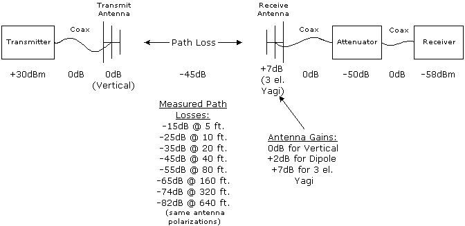
The above path losses were measured at various times with the transmitter being an ammo box sitting on the ground with a 19" quarter wave whip antenna. By having the transmitter on or close to the ground the path loss is more like 10dB for a doubling of distance rather than the theoretical 6dB. Measurements were done in the woods, on grass, and pavement with the results averaged for the table above.
The example shown above shows:
A 1W transmitter connected through lossless coax to a vertical. The receiver is connected through lossless coax to a 50dB attenuator which is connected through lossless coax to a 3 element yagi which is 40 ft. from the transmitter. The received signal strength is ~ -58dBm.
A proven combination active/passive 1 knob attenuator is shown on on the next page.
Page content last updated Mar. 12, 2008
Copyright © 2008 Larry Benko, W0QE
