What is the UHF Connector?
The UHF connector that is commonly used in amateur radio applications at frequencies below 450MHz is not a true 50 ohm constant impedance design as are N, BNC, SMA, TNC, etc. connectors (N & BNC are also available in 75 ohm versions). The center conductor is too large in diameter for the connector body size resulting in part of the connector appearing to be an impedance significantly less than 50 ohms.
The following are some measurements and calculations showing the effects of a mated UHF connection versus frequency. It only makes sense to talk about mated connections since the PL-259 (male) and SO-239 (female) are always paired together.
The picture below shows 3 connectors that I carefully machined in half showing the connector details.
Page content last updated Nov. 13, 2013
Copyright © 2013 Larry Benko, W0QE
UHF Connector Need for Compensation
Some estimating
For my mated Teflon PL-259 and the Amphenol SO-239 "D" average = 0.48", "d" average = 0.170", er = 3.5
resulting in Zo = 33.3 ohms
For my mated Teflon PL-259 and my teflon SO-239 "D" average = 0.48", "d" average = 0.200", er = 2.1
resulting in Zo = 36.2 ohms
Notice how the advantage of the lower dielectric constant Teflon (raises Zo) is nearly offset by the larger center pin diameter (lowers Zo).
Both mated connection impedance error sections are 1.03" in length. However they have different electrical lengths since the velocity factor is 1 divided by the square root of the relative dielectric constant so the final estimates are:
For my mated Teflon PL-259 and the Amphenol SO-239 = 1.93" electrical length of 33.2 ohm transmission line and for my mated Teflon PL-259 and my Teflon SO-239 = 1.49" electrical length of 36.2 ohm transmission line.
Conclusions
The strengths of a quality made UHF connector are the large center pin which can handle significant power and the relative inexpensive cost. The down side of an incorrect impedance are either not worth worrying about or are easy to compensate for at frequencies less than 500MHz. I have a 2m/70cm radio using a UHF connector which uses the exact compensation I mentioned above. Also you can buy SO-239 connectors with a mostly air dielectric. The large center pin with a relative dielectric of something like 1.3 would raise the impedance to 46 ohms and be much less of an issue. These are occasionally seen on VHF SWR meters.

approximately 1.0 for air, 2.1 for Teflon, 4.4-5.4 for bakelite (phenolic), 3.6 for Delrin (acetal), 2.2 for solid polyethylene, and all plastics that I know of are between 2.1 and 6.0. Relative dielectric constants do change slightly with frequency but that is beyond the scope of this analysis.
Be careful when assuming the connector is Teflon. Many connectors (even from Amphenol) come in both Teflon and white Delrin dielectric material. You need to look very closely. Delrin will melt with a soldering iron and is a slightly different shade of white.
The physical dimensions for the 3 connectors in the picture above are:
PL-259: 0.43" < D < 0.47", d = 0.159", length of impedance error 0.25" but insulator only occupies 0.16" completely and 0.09" partially
Amphenol SO-239: 0.46" < D < 0.50", 0.137" < d < 0.196", length of impedance error 0.77"
Teflon SO-239: 0.46" < D < 0.50", 0.19" < d < 0.25", length of impedance error 0.77"
The overall length of the impedance error for a mated PL-259/SO-239 is 1.03". This means the SO-239 is responsible for ~3/4 of the total error. The diameters need to change slightly throughout the connector in order to keep the connector from coming apart.
The formula below is well known and is used to calculate the characteristic or surge impedance of a coaxial structure.
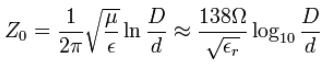
Where "D" is the inside diameter of the shield, "d" is the outside diameter of the inner conductor, and "er" is the relative dielectric constant. Relative dielectric constants vary for materials and are
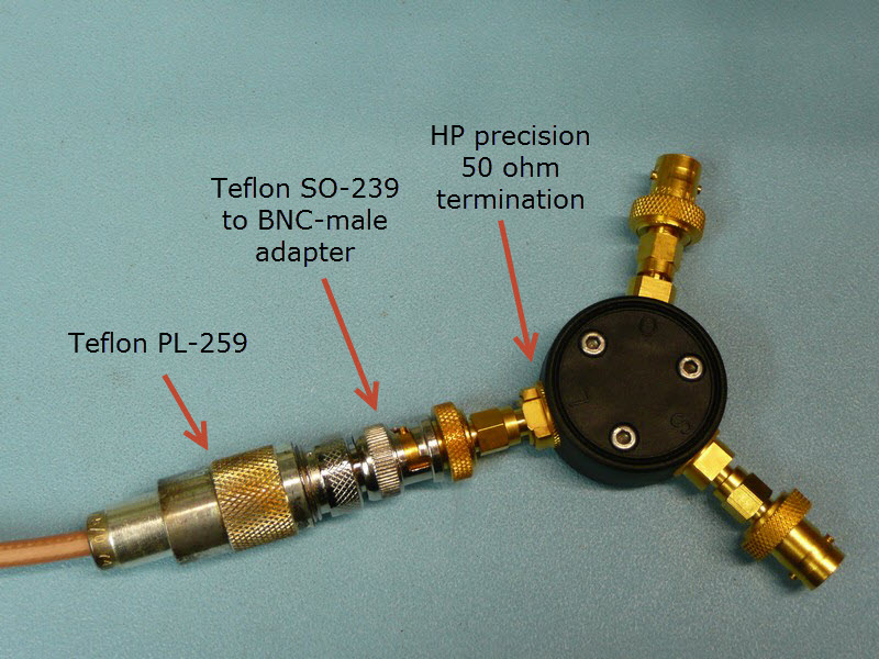
VNA Measurement
I carefully calibrated an 8753 VNA from 0.3 to 500MHz and made 2 measurements. The first was my Teflon PL-259 mated to a Teflon SO-239 to BNC-male adapter connected to an HP precision 50 ohm termination. The second was my Teflon PL-259 connected to my Teflon SO-239 with four 200 ohm 0.5% 1/4W resistors soldered from the center pin to the flange with lead < 0.1" long.
I received a comment from Dave Kirkby, G8WRB asking about the effect of the SMA to BNC adapter on the results. I didn't initially mention it but I cascaded two of these adapters (SMA-m to BNC-f and SMA-f to BNC-m) in series with the initial calibration and only saw the SWR rise to 1.05:1 at 500MHz. Therefore I feel the effect of only one adapter is insignificant and can be ignored for the technical level of this web page.
The above 2 traces are very similar but I am going to assume that the bottom trace with the adapter and the precision termination is more accurate than my four resistor load. For the above measurement the SWR at 30/100/500 Mhz is respectively 1.0195:1/1.0627:1/1.2804:1.
These SWRs may be low enough that there is absolutely no need for improvement.
These SWRs may be low enough that there is absolutely no need for improvement.
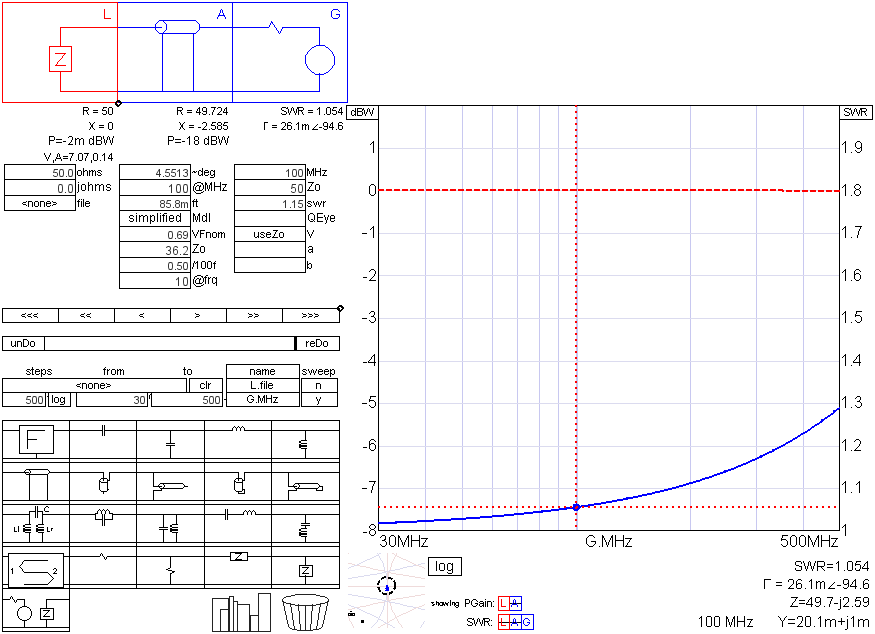
Calculations
The figure below show the results of the very useful and free SimSmith program. The calculated SWRs using the above measured estimates of the Teflon PL-259 mated to the Teflon SO-239 to be 1.016:1/1.054:1/1.287:1 at 30/100/500MHz respectively. The agreement with the measured values is extremely close.
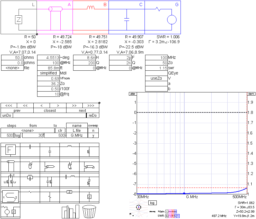
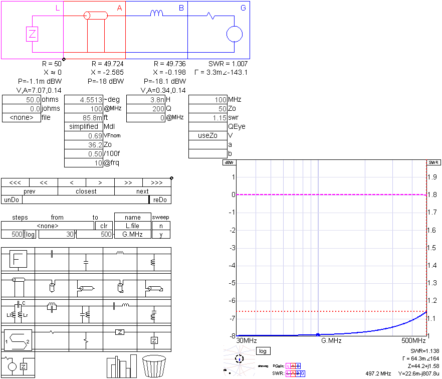
Are Improvements Possible
The figures below show the results of a wire ~1/2" long (3.8nH) in series with the SO-239. Now the SWR at 500MHz is 1.138:1. If additional improvement is desired a capacitor of 2pF and a lengthening of the wire to 8.6nH produces an SWR of 1.062:1 at 500 Mhz with the SWRs at lower frequencies being virtually nil.