Using non-RF rated relays for RF applications
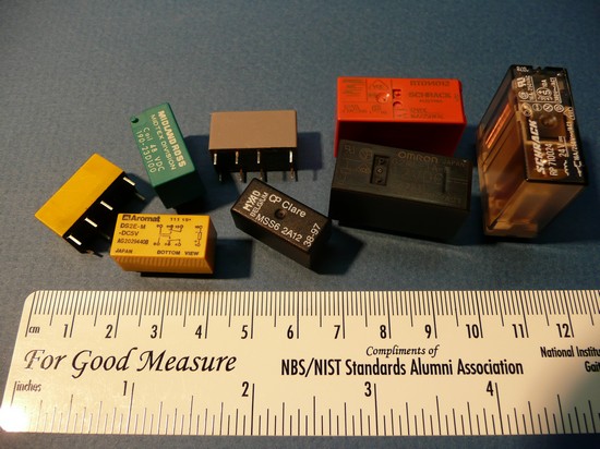
I have often used small signal/control relays such as the 5 on left side of the picture for RF use through the low VHF range for receive applications and at power levels less than 10W. They are nominally 3ms operate/release, very quiet, and have been reliable. The 3 relays on the right side of the picture are rated at 12/16A and have been found to be reliable at 1500W in the HF range but they are considerably noisier than the smaller relays, operate in the 6ms range, and are not rated for use in "dry" circuits (think receive). Due to the contact material they may work fine when new but become unreliable in time.
I had a specific application in mind and decided to do some tests which might be of interest to others.
I had a specific application in mind and decided to do some tests which might be of interest to others.
Page content last updated Oct. 29, 2012
Copyright © 2012 Larry Benko, W0QE
Using Small Signal Relays at RF
Problem
I wanted to use an inexpensive (non-vacuum relay) to insert an attenuator in front of a high power HF amplifier for protection of the amplifier. The attenuator would be hot switched in during times of excessive drive or high reflected output power. This relay which would need to operate very quickly at power levels of up to 200W and be reliable. I considered PIN diodes rather than relays due to speed but wanted to exhaust relay choices before going the route of bias voltages etc. to control the PIN diodes.
The 5 relays on the left side of the picture are relays made popular by the telecommunications industry for analog telephone circuits and also by the security industry. These relays have an operating current rating from 10uA to 2A and usually are 2 form C contacts (double pole double throw, break before make contacts). The contacts are also bifurcated (2 smaller contacts on each pole) which increases the reliability greatly for low current use and the relays have mechanical life expectancies of 10 to 20 million operations. These relays are made by several different companies but some of the past suppliers were bought by Tyco Electronics which is now TE Connectivity. Additionally Panasonic used to sell relays under the Aromat and later as NAIS names but are now labelled Panasonic. These relays have a footprint that matches a dual inline IC, cost approximately $2.50 to $3.50 in single quantities, and are available from suppliers such as Mouser, Digikey, Allied, etc.
Examples of the small signal relays are:
Panasonic (Aromat/NAIS) DS2E-M-DCxxV or DS2E-M-DCxxV (click for PDF data sheet)
Omron G5V-2-xxx or G5V-2-H-xxx (click for PDF data sheet)
Omron G6S-2 (click for PDF data sheet)
TE Connectivity (Tyco, P&B, CP Clare, Axicom) D3002
Similar relays from American Zettler, Fujitsu, NEC etc.
The 3 larger relays on the right side of the picture above are only shown for reference and were not tested.
Examples of the larger relays are:
TE Connectivity (Schrack) RTD140xx (click here for data sheet)
Omron G2RL-xxx (click for PDF datasheet)
TE Connectivity (Schrack) RT31C0xx (click here for data sheet) This relay has bifurcated contacts!
The relay I tested was a Panasonic DS2E-M-DC12 and prior to starting the test, the resistance of both contacts on each pole of the relay were measured at a 1A DC level per the data sheet. All 4 measurements were between 20 and 23 milliohms which was slightly less than one half the 50 milliohm spec. The transmitter/amplifier was keyed by the keyer at a 100% duty cycle while also keying the relay in the attenuator at a 30ms on/off (40 wpm) rate making for a hot switching test. The exciter was keyed for about 30 seconds on and 30 seconds off and the tests were run for several hours. The output of the attenuator was connected to a 50 ohm dummy load. I started at lower powers and increased the stresses.
Tests
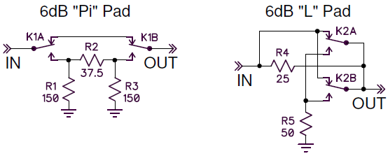
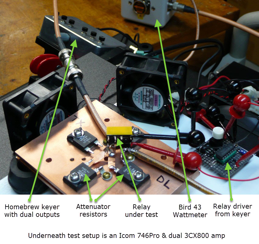
The schematic drawings below show 2 possible attenuator topologies. Both are 6dB and both provide a 50 ohm impedance to the driving source in the steady state. However the "Pi" attenuator requires an input and output pole and is a terrible match to the driving source during the switching time. The "L" attenuator provides a good 1.5:1 SWR during the switching period and both poles of the relay can be doubled up to enhance reliability (2 poles with bifurcated contacts = 4 contact points). The "L" attenuator provides a 25 ohm impedance as seen looking back from the output but this is not a concern. The picture below shows the actual test setup used with the "L" pad.
1.) 300,000 cycles @ 100W (14Mhz)
Relay disconnected and all contact resistances were between 20 and 23 milliohms.
2.) 50,000 cycles @ 220W (14Mhz)
3.) 10,000 cycles @ 300W (14Mhz)
4.) 10,000 cycles @ 400W (14Mhz)
5.) 10,000 cycles @ 600W (14Mhz)
6.) 100,000 cycles @ 100W (14Mhz)
Relay disconnected and all contact resistances were still between 20 and 23 milliohms.
Relay case was carefully machined away and contacts were examined under a microscope.
Minor contact scarring was observed.
This successfully concluded the attenuator tests.
Additional tests with same relay
The attenuator tests have different voltages/currents compared to a contact that is just opening and closing an RF path. For this test I connected the transmitter/amplifier output to the relay contact which was connected to a dummy load directly. The amplifier was loaded to produce 1000W output but was driven at a much lower level which did not trip the reflected power circuitry in the amplifier when hot switching the output.
7.) 100,000 cycles @ 100W (14Mhz), both contacts in parallel doing the switching
Relay disconnected and all contact resistances were between 20 and 25 milliohms
8.) 100,000 cycles @ 100W (14Mhz), single contact only
9.) 10,000 cycles @ 250W (28Mhz), single contact only (higher power and higher frequency)
Relay disconnected and all contact resistances were between 20 and 28 milliohms
Moderate contact scarring was observed but contact resistances still in spec.
10.) 1000 cycles at low speed with a 1 kHz AC current of 1uA to simulate a receive condition.
No cases of a high contact resistance were observed (this is why bifurcated contacts were designed).
Conclusions
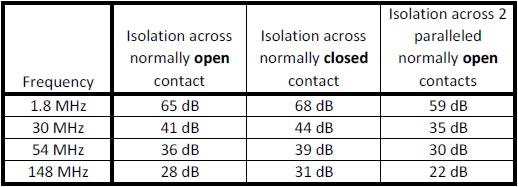
After hot switching the relay 700,000 cycles at various powers the relay still operated well and the contact resistance was within spec. Granted this was a test of a single relay but the outcome was better than I expected and 100% hot switching a huge number of times is not typical. In some cases the relay isolation as measured in a 50 ohm environment might be an issue unless secondary contacts are used to shunt the RF path in addition to opening it. The isolation numbers are close to 0.5pF of capacitance per contact. Using a shunt contact increased the isolation to 80dB at 30MHz. Hopefully this information might be useful to others.