Testing of power amplifiers for amateur radio use was the result of my need to understand why some amplifiers
sound much cleaner on the air prior to building another amplifier. Amplifiers for CW or FM usage do not need to be
linear but the requirement for SSB is to have a linear amplifier necessitating a procedure to quantify the linearity of
the amplifier. The most common test is to drive the amplifier with 2 closely spaced frequencies (e.g. f1 & f2) that
are not harmonically related and measure what additional frequencies are generated in the output. The newly
generated undesirable frequencies (2*f1-f2, 2*f2-f1, etc.) are collectively called intermodulation distortion or IMD.
Wikipedia has a very good page explaining the undesirable process of intermodulation distortion which is caused by
the amplifier not being perfectly linear.
Procedure:
1.) Generate 2 equal amplitude continuous wave (CW) frequencies that are not harmonically related that drive the
amplifier to the maximum peak level you intend to run the amplifier. The frequencies are generally separated by
1200Hz for amateur radio use for historic reasons but could easily be 2kHz or 10kHz apart if that makes the
detection easier.
2.) Tune or adjust the amplifier if necessary.
3.) Attenuate the amplifier output if necessary and measure with a spectrum analyzer, calibrated receiver, or
receiver with preceding calibrated step attenuator the newly produced undesirable frequencies. If the 2 driving
frequencies are separated by 2kHz then the 2 strongest undesirable outputs will occur at 2kHz below the lower
driving frequency and 2kHz above the higher driving frequency. Additional lower level outputs will occur at 4kHz,
6kHz, 8kHz etc. above and below the driving frequencies.
Note: Industry measures the ratio of the weakest desirable output (they both should be the same) to the
strongest undesirable frequency (closest to one of the desirable frequencies) as a ratio in decibels (dB) and calls
this number the IMD value. However the American Radio Relay League refers the the undesirable strongest output
to the peak power in both desirable outputs resulting in a number that is 6dB larger than industry numbers.
Darn Details:
It was not mentioned above but generating only 2 frequencies to drive the amplifier is not a trivial matter. The
driving signals will also contain their own IMD products due to the combining or mixing and the source needs to be
much better from an IMD distortion point of view than the amplifier we are testing. Generally the source should
have an IMD value at least 6dB better than the amplifier under test.
My Solution:
Many of us have several old transmitters that can be operated in the CW mode and have power outputs of 100W
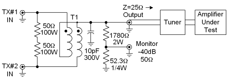
or more which will generate a single frequency very cleanly. I built a power combiner capable of combining two
100W signals and paid close attention to symmetry. The circuit below shows a Magic-Tee combiner without an
output transformer to convert the output to a 50 ohm impedance. The measured isolation from either transmit
port to the other, with the output terminated in 25 ohms, was 35.5dB @ 1.8MHz, 33.6dB @ 14MHz, and 23.0dB
@50MHz. Attempting to use this circuit as a generator for IMD tests was a disaster. Enough signal was
coupled from transmitter #1 into the output of transmitter #2 and vice versa that the resulting IMD was
unacceptable. Even if I was capable of building a perfect combiner with infinite isolation between the transmit ports
and a 50 ohm output port, amplifiers which have input impedances of not exactly 50 ohms would disrupt the
infinite isolation. The solution to the problem was to add a tuner between the combiner output and the amplifier,
matching the ~25 ohm output impedance of the combiner to the input impedance of the amplifier and providing
isolation to the combiner for changes in input impedance throughout the RF cycle from the amplifier under test.
Generating the 2 Frequencies:
1.) The traditional method is to drive a transmitter, capable of generating enough power to drive the amplifier to
the proper output level, operating in the SSB mode with 2 precise audio sine waves, usually at 700Hz and 1900Hz.
This method assumes that the driving transmitter has much better IMD than the amplifier under test and that there
is no appreciable carrier frequency or opposite sideband output. Very few current production transmitters, other
than some Yaesu models operating in class A, have good enough IMD to test a high quality amplifier.
2.) Another method is to start with 2 crystal oscillator or very clean RF signal generator sources and combine
them with a power combiner and additional resistive padding to not generate appreciable IMD and follow this weak
signal with a large class A amplifier. This method is referred to in old Eimac documentation where the class A
driving amplifier was often larger than the tube being tested to ensure good linearity and IMD.
Even if you are able to generate a clean signal to drive the amplifier, the input impedance of the amplifier may vary
throughout the RF cycle causing the generating source to produce IMD products. This may also happen to a real
transmitter to a larger or smaller extent than in the test setup when driving an amplifier. This is why many
amplifiers have front end pads or LC matching networks to smooth out the impedance.
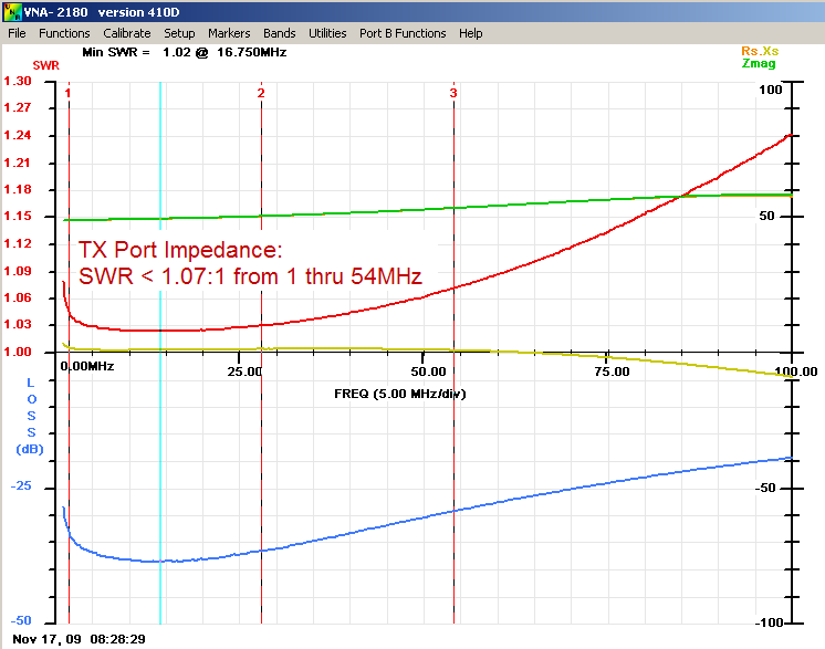
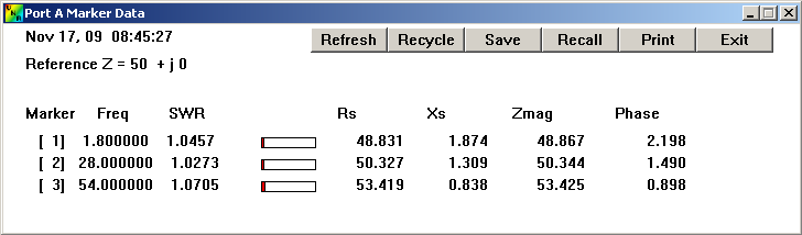
SWR at either transmit port with output terminated in 25 ohms
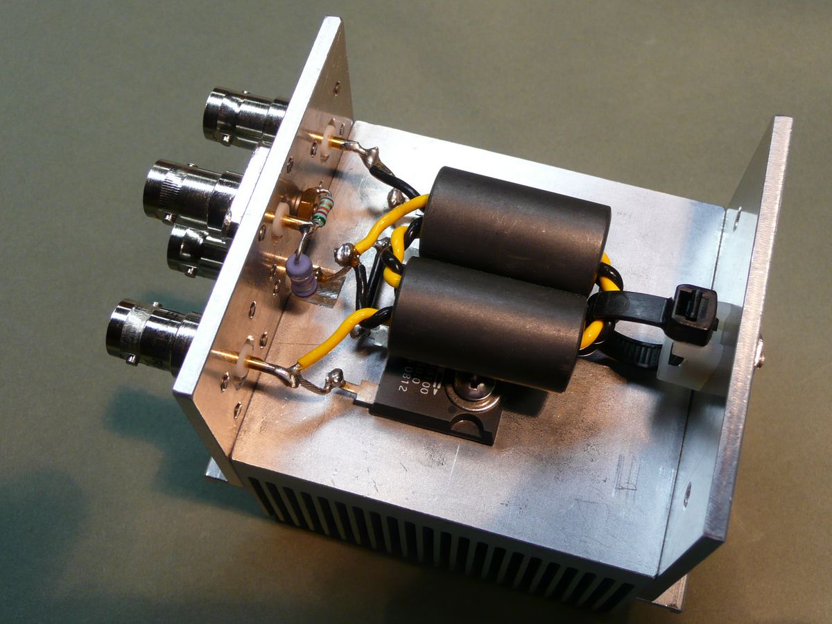
Click on either picture for higher resolution image
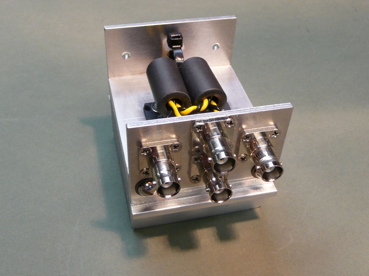
T1 consists of 2 turns of two #18 twisted teflon wires wound thru 2 FairRite #2643625102 #43 cores (.625"OD x .312"ID x 1.125"L). The 50 ohm resistors are Caddock type MP9100 since half the power is lost when the two inputs are not the same frequency and phase. Photos were taken before the 10pF capacitor was added which improves the input impedance for the 2 TX ports.
Spectrum plot of two 50W combined signals (200W peak) at 14.099 & 14.101 MHz showing IMD of 64dB relative to single tone (70dB ARRL method). An IC-706mkIIG was being operated at 100W on 14.099MHz and the IC-7000 was being operated at 100W on 14.101MHz.
Page content last updated Nov. 17, 2009
Copyright © 2009 Larry Benko, W0QE
Test Procedure:
1.) Decide on the frequencies to use for the IMD testing. In this example I used 14.099MHz and 14.101MHz.
2.) Drive the amplifier under test from one of the radios directly tuning up the amp into a dummy load or high
power attenuator.
3.) Connect one transmitter to the power combiner which is connected to the tuner which then connects to the
amplifier under test. Set the power level of the transmitter to the lowest possible value and adjust the tuner for
minimum signal received at the other transmit port. This will easily raise the isolation in the combiner to 40dB or
more and with a little care can be made to be upwards of 70dB. No tuner adjustments were needed when
reversing the transmit ports due to building the combiner very symmetrically.
Caution!! If the 2 transmitters being used are transceivers they both need to be put into the "transmit
mode" before actually transmitting any RF from either one or one of the receivers may be damaged.
For my tests I used an Icom 706mkIIG and an Icom 7000 and built a cable that had 3 positions: both
radios in receive mode, both radios PTT active and in transmit mode with no RF output, both radios
keyed in CW mode generating RF power.
4.) The monitor port on the combiner can be used to watch the IMD distortion of the source driving the amplifier
under test. If this port is used it should be connected to a 50 ohm termination during tuner adjustment as it has a
small effect on the isolation of the combiner.
5.) Setting the power output of both radios to 50W is exactly the same as driving a perfect 100W transmitter
with a 2 tone equal amplitude audio input. Set the power on both transmitters to drive the amplifier to the proper
output level.
Results:
The following two graphs show the resulting IMD and the input SWR for the transmitting ports. The IMD levels are
good enough to test class A amplifiers if needed. I was very pleased with the results.
IMD = 64dB
(70dB ARRL method)
(70dB ARRL method)
Monitor port may appear to be -37dB relative to the output port but is -40dB due to the different port impedances