Background
Grow Light Electronic Ballasts
Page content Nov. 19, 2011 and updated Feb. 7, 2012
Copyright © 2011-2012 Larry Benko, W0QE
Click on any picture for larger image
| Distance | Configuration | Increase in noise floor @ 7 MHz |
| ~800 ft. | 1 ballast (LK1000) |
+12 dB |
| ~600 ft. | 2 ballasts (LK1000s) |
+12 dB |
| ~480 ft. | 1 ballast (unknown model) |
+12 dB |
| ~2500 ft. | 8 ballasts (unknown models) |
+6 dB |
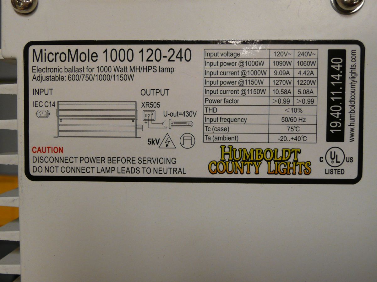
| ~700 ft. | 1 ballast (MicroMole 1000) |
+24 dB |
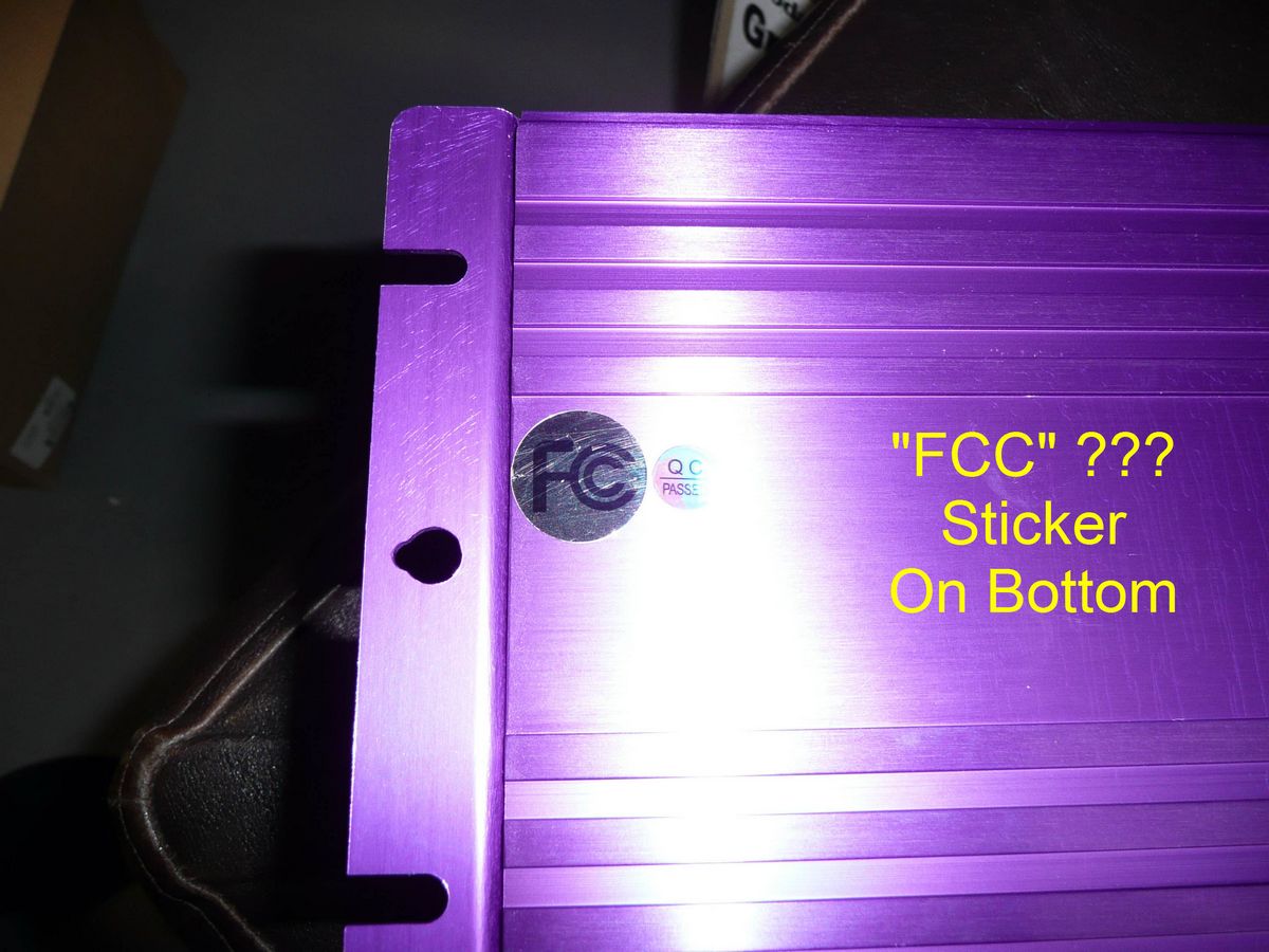
Operations wishing to grow plants indoors need to provide supplemental lighting necessary for photo-synthesis. These lights may be flourescent, LED, and for larger operations high pressure sodium (HPS) or metal halide (MH). The HPS and MH lamps may be 1000W per lamp and require a ballast for proper operation. These ballasts were originally magnetic but in the past few years have become electronic. These devices are subject to FCC part 18 rules but there appears to be a total disregard for the FCC rules. These electronic ballasts are manufactured in China and may have little "FCC" stickers on them but there is no evidence of any testing for compliance having been done. The proliferation of "grow" and "hydroponic" stores everywhere which sell these electronic ballasts in nice glossy color packaging to non-industrial users means that these devices need to meet the consumer limits of FCC part 18 in order to be legal.
Tom, W0IVJ began seeing instances of significant noise on 40 meters (7 MHz) in June 2010 and in the past 17 months we have identified 5 grow operations near his location. The amount of noise produced by these devices is larger than anything I have ever measured. The following table shows the increase in noise level on 40 meters for a city lot where the base noise is about S5. We have either reduced the noise via filters or caused these operations to move due to threat by the landlord or the fact that these electronic ballasts produce so much noise that anyone with an AM radio can tell what is going on inside a home. Being anonymous and trying to fly under "the radar" is not easy when you are generating this much RF interference. The fourth item in the table was 1/2 mile away and still was easily heard on 40 meters.
Tom, W0IVJ began seeing instances of significant noise on 40 meters (7 MHz) in June 2010 and in the past 17 months we have identified 5 grow operations near his location. The amount of noise produced by these devices is larger than anything I have ever measured. The following table shows the increase in noise level on 40 meters for a city lot where the base noise is about S5. We have either reduced the noise via filters or caused these operations to move due to threat by the landlord or the fact that these electronic ballasts produce so much noise that anyone with an AM radio can tell what is going on inside a home. Being anonymous and trying to fly under "the radar" is not easy when you are generating this much RF interference. The fourth item in the table was 1/2 mile away and still was easily heard on 40 meters.
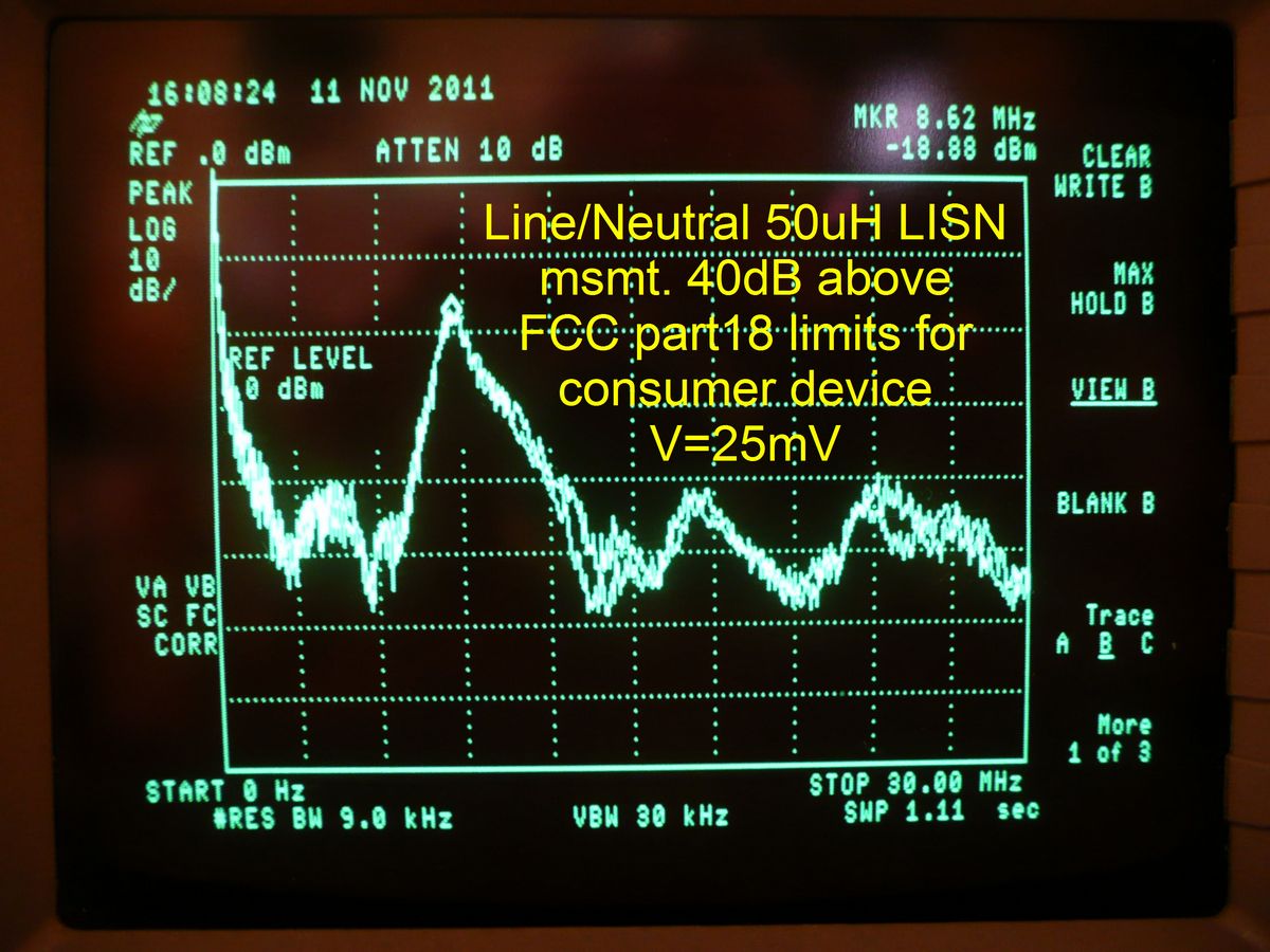
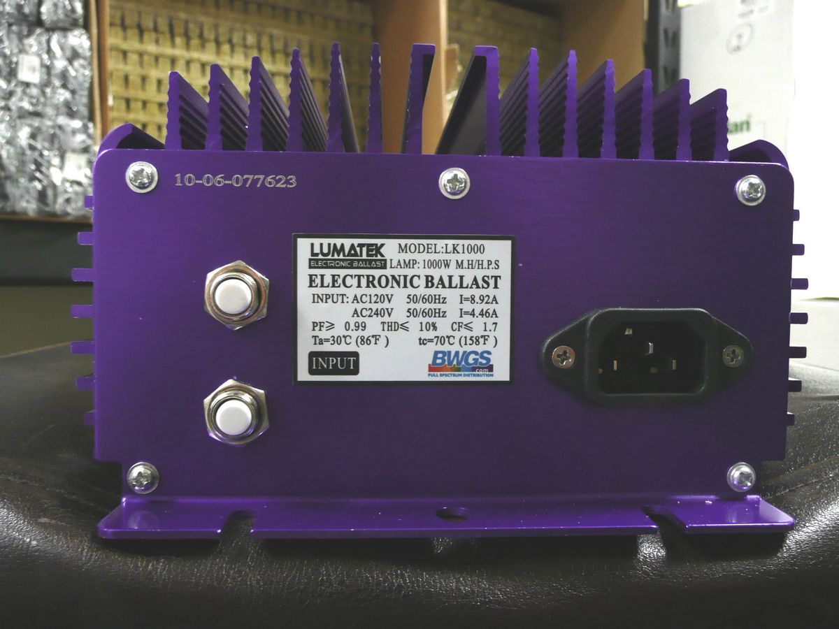
We have befriended the owner of a local grow store who graciously let us make measurements on a Lumatek LK-1000 electronic ballast connected to a 1000W high pressure sodium lamp. We used an industry standard 50uH LISN (line impedance standardization network) as required in FCC part 18. We used a spectrum analyzer with a 9KHz bandwidth and a quasi-peak detector again as required in FCC part 18. We made the measurements at the grow store and were unable to connect the LISN directly to earth ground as would be done at a testing lab but the results should be close to what a lab would get. Additionally we measured the actual common mode current on the AC line to the electronic ballast which is a measure of the RF interference.
Measurements
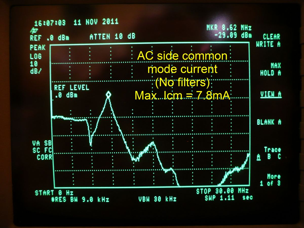
The following measurements were made on Nov. 11, 2011 on a brand new Lumatek LK-1000 electronic ballast. This unit exceeds the FCC part 18 limits for a consumer device (250uV for consumer device) by 40 dB and the common mode current was a maximum of 7.8mA at 8.62 MHz as measured with a F-33-4 Fischer Custom Communications current probe. Generally the common mode current of most well designed equipment is in the range or 1-5uA. I have never heard any interference from a device if the common mode current was below 1uA and 7.8mA is 77.8dB above 1uA. These are huge levels of RF interference. Notice the bogus "FCC" sticker on the bottom of the unit.
The Fix
Attempts to tame the RF interference from these electronic ballasts is much more than wrapping just a few turns through a torroid. We were able to borrow a MicroMole 1000 ballast, 1000W HPS lamp, and set it up in the basement of W0IVJ. The RF interference on 40 meters (7 MHz) was a constant S9+25dB as measured using an outside dipole at a distance of about 40 ft. and a Flex-1000 SDR. We focused on 40 meters where the interference was the worst but all HF bands were obliterated. These measurements were made on Nov. 7, 2011.
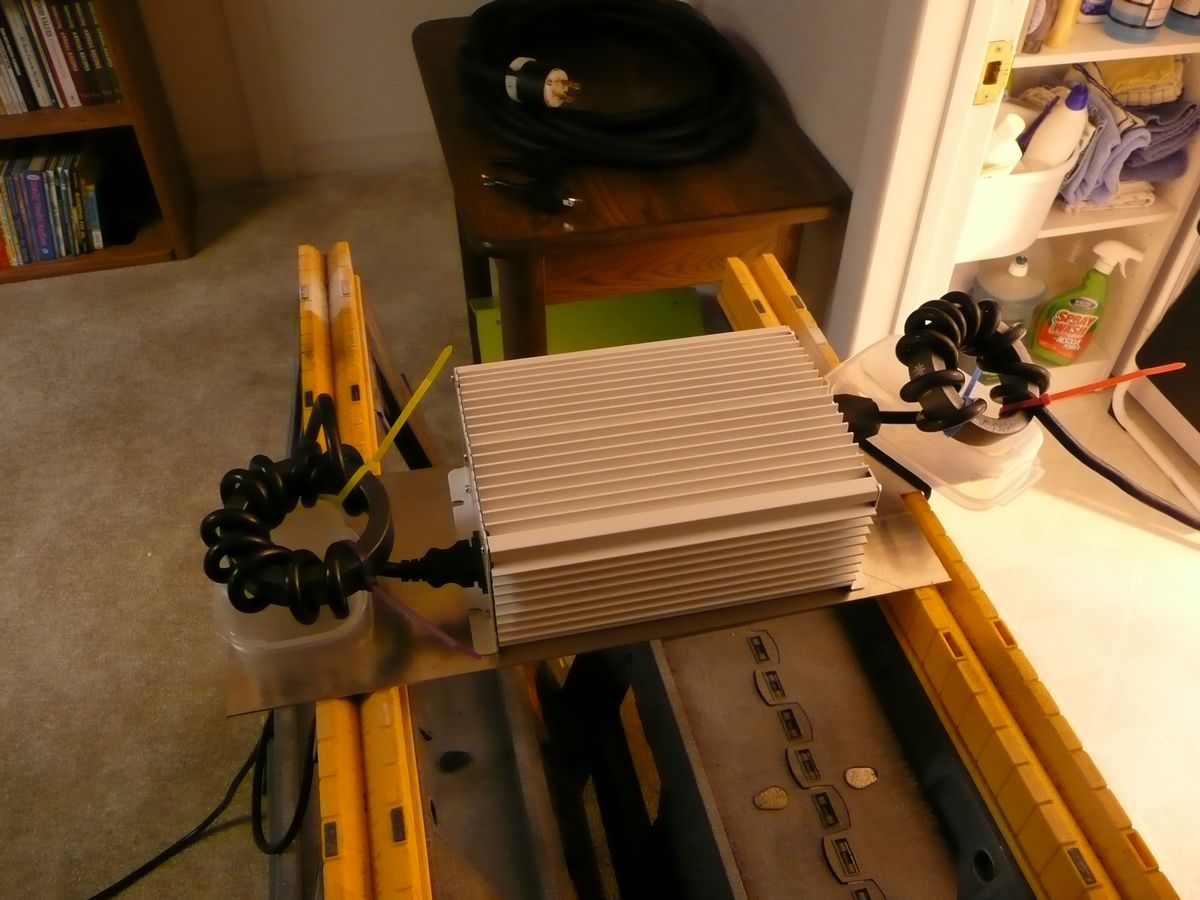
We wound 10 turns of the input and output cables through very large #31 toroids (Fair-Rite #2631814002) which are 4"O.D. These common mode chokes (CM impedance measured >2000 ohms) reduced the interference 15dB to S9+10dB which was still terrible. Building a filter for the AC line which consisted of a good common mode choke on just the Line and Neutral wires and 4700pF 250VAC rated caps to the safety ground/chassis (still big toroid on output) reduced the interference to S8. Finally building an output filter similar to the AC input one reduced the interference to below the ambient level of S5. However the output filter ran quite warm and the capacitors on the output needed to be much higher voltage if the product label of 5kV is to be believed.
Click on any picture for larger image
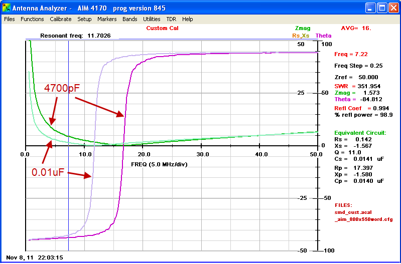
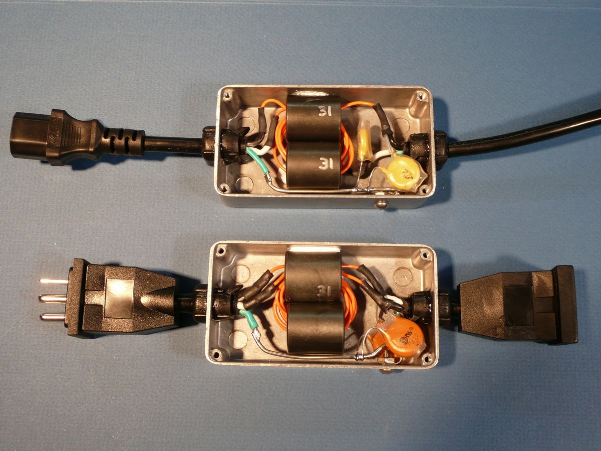
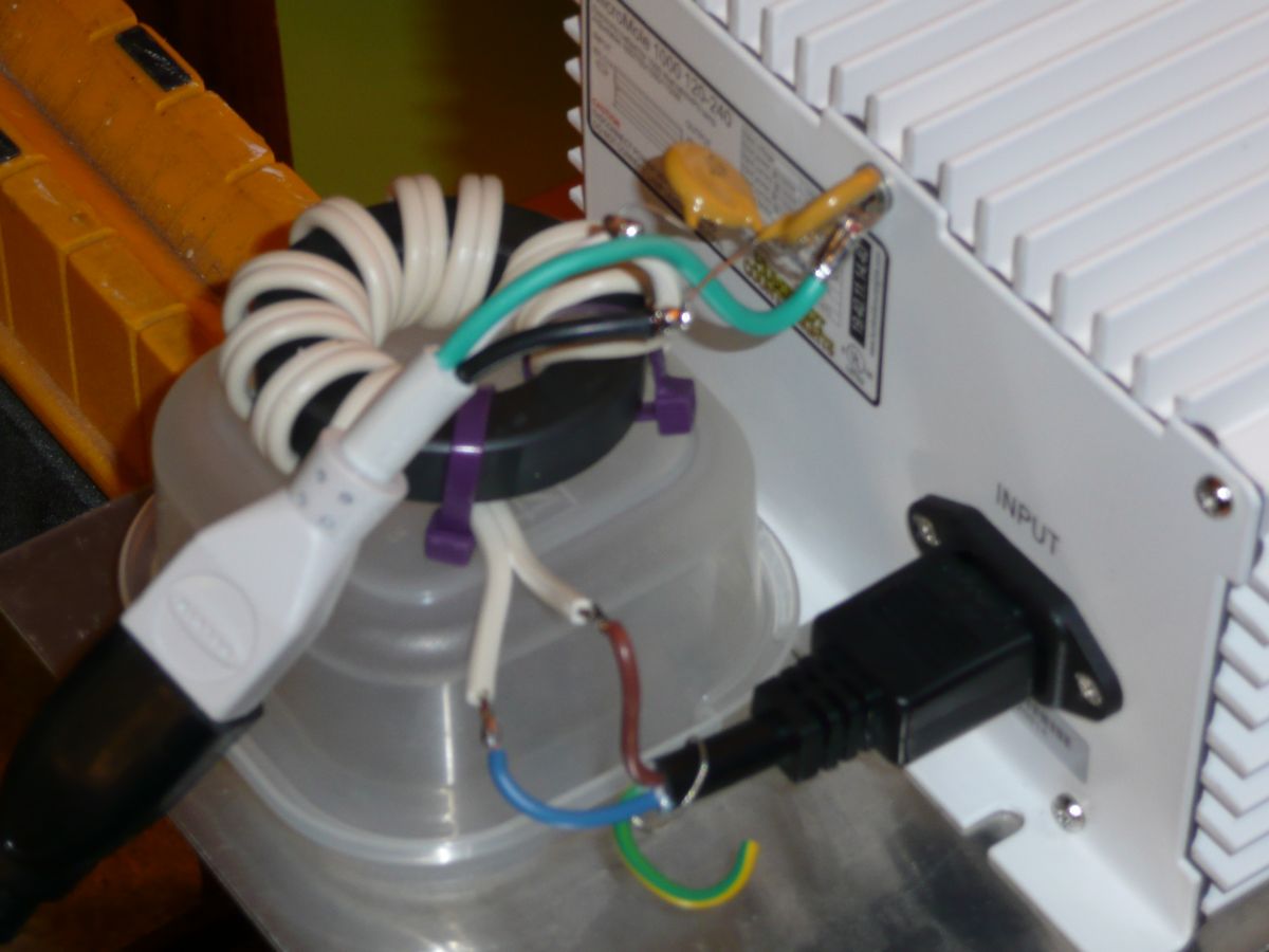
Measurements of the components used in the filters and the filters in boxes are shown below. The orange wire is #18 teflon 200 deg. C wire. The input filter ran cold but the output filter ran very warm and will need to be improved before put into actual use.
Click on any picture for larger image
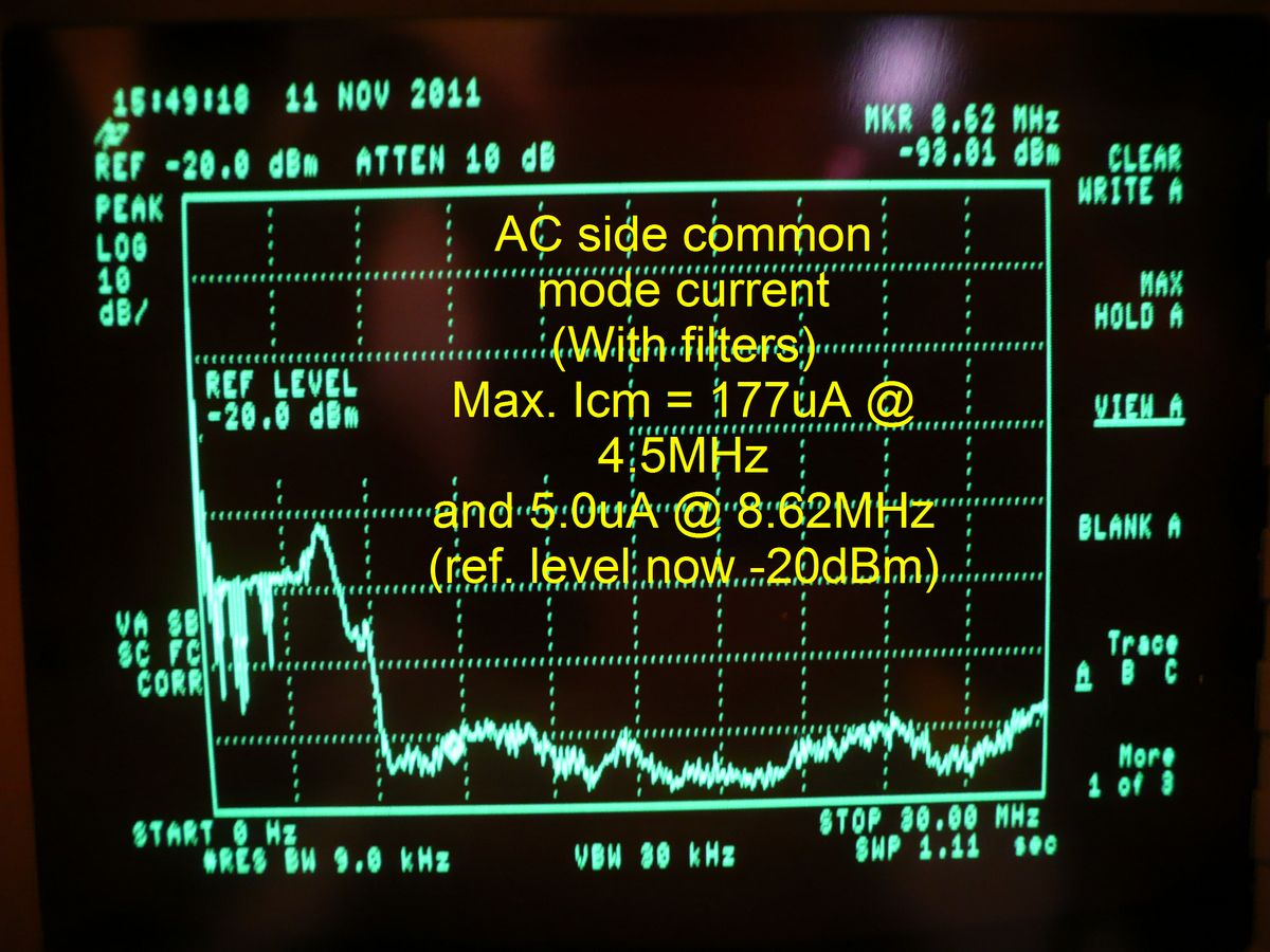
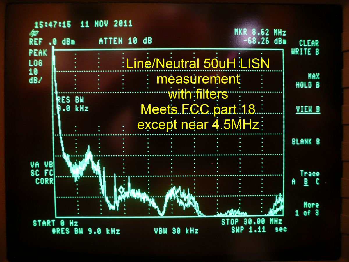
On Nov. 11, 2011 while we were making measurements at the local grow store we also made measurements on the Lumatek LK-1000 with the filters. The top 2 pictures are repeated from the top of this page and show the "belore" interference levels and the lower 2 show the interference with the filters installed.
While the above measurements were being made a small shortwave receiver was placed at the check out counter in the grow store. Turning on the Lumatek LK-1000 without filters rendered the radio completely useless and with the filters the noise heard on the radio was no different than when the LK-1000 was turned off. Once we properly change the output filter so that it does not heat up we will be quite happy at the results but are still extremely dismayed that these kinds of products are allowed to be sold without consequences to the manufacturer.
Final Solution
The actual MicroMole 1000 ballast that was causing W0IVJ interference was borrowed for an additional day. The output filter that is shown above also ran very warm with this uint. The heat in the filter was from the toroids and not the teflon wire or the capacitors.
The voltage from each output (lamp side) wire to chassis (green wire ground) was measured at +/-2500Vpk at a frequency of 100KHz. The wave form looks much like an undercompensated oscilloscope probe measuring a square wave. The square wave amplitude was about +/-500V with the +/-2500V overshoot occurring at the leading edges of the square wave and lasting for about 20% of the waveform period before reaching the 500V level.
Disconnecting the capacitors reduced the heat in the output filter to less that the temperature of the ballast itself. This was decided to be the final decision since the ballast needed to be returned and the noise was suppressed enough that for distances greater than 50 ft. it was unable to be heard.
I have received numerous inqueries about the filters and what parts to use so here are what I would currently build for the filters:
AC Side Filter
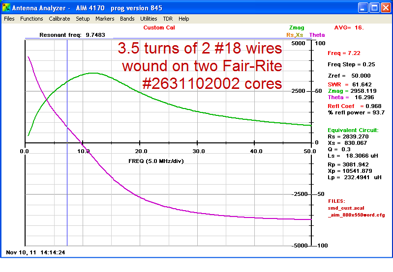
Wind the Hot and Neutral (NOT the safety ground) wires through 2 toroids 3 1/2 times. One toroid get 4 passes of the wires and the other on gets 3 passes. This is done for physical reasons only. On the AC input side there are 2 capacitors from the Hot wire to safety ground and from the Neutral wire to safety ground. The previous picture shows the detail of the construction. The safety ground wire connects to one side of the capacitors and does not pass through the toroids. All the parts are available from Mouser Electronics at www.mouser.com. The 2 toroids are part #623-2631102002 @ $1.90ea. (1.02"OD x 0.505"ID x 1.125"long #31 material) and the 2 capacitors are part #72-VY2103M63Y5UG63V0 @ $0.29ea. (0.01uF 300VAC rated capacitors).
Lamp Side Filter
To avoid heating of the toroid core(s) the capacitors are not used. A filter similar to the AC side filter without the capacitors works well. However if the source of the interference is within a few hundred feet you you may wish to use a larger toroid. In this case part #623-2631803802 @ $7.00ea. (2.4"OD x 1.4"ID x 0.5"high #31 material) is a much larger toroid and only 1 toroid is needed with the 2 lamp wires passing through the toroid 8-10 times. The safety ground wire does not pass through the toroid.
AC Side Filter
Wind the Hot and Neutral (NOT the safety ground) wires through 2 toroids 3 1/2 times. One toroid get 4 passes of the wires and the other on gets 3 passes. This is done for physical reasons only. On the AC input side there are 2 capacitors from the Hot wire to safety ground and from the Neutral wire to safety ground. The previous picture shows the detail of the construction. The safety ground wire connects to one side of the capacitors and does not pass through the toroids. All the parts are available from Mouser Electronics at www.mouser.com. The 2 toroids are part #623-2631102002 @ $1.90ea. (1.02"OD x 0.505"ID x 1.125"long #31 material) and the 2 capacitors are part #72-VY2103M63Y5UG63V0 @ $0.29ea. (0.01uF 300VAC rated capacitors).
Lamp Side Filter
To avoid heating of the toroid core(s) the capacitors are not used. A filter similar to the AC side filter without the capacitors works well. However if the source of the interference is within a few hundred feet you you may wish to use a larger toroid. In this case part #623-2631803802 @ $7.00ea. (2.4"OD x 1.4"ID x 0.5"high #31 material) is a much larger toroid and only 1 toroid is needed with the 2 lamp wires passing through the toroid 8-10 times. The safety ground wire does not pass through the toroid.