Easy to do Design
Crystal Bandpass Filters
Page content last updated Sep. 16, 2011
Copyright © 2011 Larry Benko, W0QE
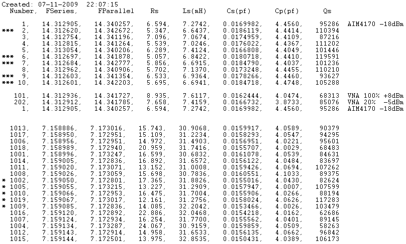
There have been articles on how to design crystal filters in magazines for years. The difficulty always centered around measuring and selecting crystals and then designing the circuit. There are several programs which can help design a crystal filter but I generally use the free AADE Filter Design program at http://www.aade.com/filter.htm which designs several types of crystal ladder filters. All the programs I have seen require the crystals to have identical parameters. The measurement of the crystal parameters has been automated in the software for the AIM 4170 VNA (also in the AIM 4170 UHF and VNA 2180). Using a small fixture with socket pins, crystals can be measured with precision at a rate of 2 to 3 per minute. Other VNA's could have the ability to automatically measure crystals but I do not know of any which have the necessary software. The table below shows the file created by the AIM 4170. Notice that all the relevant crystal parameters are included. I generally match crystals first on Fs, Fp, and Q.
In the above listing, crystals marked *** show the five 20m crystals and * show the five 40m crystals I used. Note lines labelled 101, 202, and 1 show the same crystal measured at different signal levels.
Beside the obvious uses in homebrew receivers and transmitters, crystal bandpass filters can be used with other test equipment to make measurements that are beyond the capabilities of the test equipment. A spectrum analyzer with an 80dB dynamic range plus a good crystal filter can make 150+dB dynamic range measurements over specific frequency ranges. See the page on Phase Noise and Overload Testing for an example or click here. Filters having passbands within the amateur radio bands are more useful for testing receivers and transmitters but common crystal frequencies must be used in order for the crystals to be inexpensive.
Assuming that you are not trying to design a crystal filter for an exact frequency, the procedure is actually quite easy to do. Crystals (not crystal oscillators) are used with the resulting filter frequency usually a few kHz different than the number stamped on the crystal case. I have found that HC-49/U crystals usually have higher Qs than the smaller HC-49/US packages. Frequencies such as 1.8432, 3.579, 3.686, 3.932, 4.000, 7.159, 7.160, 7.328, 10.000, 14.318, 18.432, and 20.48MHz are common. Also consider some of the special crystal runs by the QRP clubs for crystals in the 7.040 to 7.060, 14.040 - 14.060, and other CW frequencies which are still reasonably priced.
I have built about a dozen filters and can design, construct and test one in a few hours. Here are the basic steps:
1.) Pick a frequency which is a common crystal frequency but near to the frequency you want. 10.000MHz crystals designed as series mode, 10pF parallel, 18pF parallel etc. all have different series resonant frequencies. The crystals cut to be used in a parallel resonant circuit will have series resonances below 10.000MHz by a few to several kHz.
2.) Buy a group of crystals to measure so that you can pick ones with similar parameters. I usually buy about 25 crystals and can easily make 2 filters.
3.) Measure and sort the crystals.
4.) Simulate the resulting filter and adjust slightly if needed.
5.) Match the filter to the desired input and output impedances using transformers or L-networks.
6.) Construct the filter using good RF construction techniques.
7.) Filter will work as expected!
What can Crystal Filters be used for?
What has Changed?
Step by Step Example
Let's design a 5 crystal ~14.318MHz bandpass filter using the values in the listing above having *** next to them. The AADE Filter Design program expects ALL the crystals to have identical parameters. I will use Rs = 5.347 ohms, Cs = 0.0186199pF, Ls = 6.6437mH (Fs = 14.312620MHz), and Cp = 4.4414pF which is an average of the 5 crystals. In the program I chose a crystal ladder filter, 5th order, Butterworth, bandwidth 3800Hz. The program produced a filter which had the 5 crystals, 7 capacitors, and expected terminal impedances of 256.1 ohms.
The filter was analyzed in LTSpice which is free and available at http://www.linear.com/designtools/software/. The circuit below is the LTSpice simulation of the original filter with 256.1 ohm terminations and below it the same filter with L-networks matching the filter to 50 ohms. The matching networks absorb capacitors C7 and C8 reducing component count. Notice how LTSpice treats crystals as capacitors with value Cs and all the other crystal parameters are parasitic properties of the capacitor. To download the LTSpice schematic click here and right click to save as. This file is a text file with a .asc suffix.
The filter was analyzed in LTSpice which is free and available at http://www.linear.com/designtools/software/. The circuit below is the LTSpice simulation of the original filter with 256.1 ohm terminations and below it the same filter with L-networks matching the filter to 50 ohms. The matching networks absorb capacitors C7 and C8 reducing component count. Notice how LTSpice treats crystals as capacitors with value Cs and all the other crystal parameters are parasitic properties of the capacitor. To download the LTSpice schematic click here and right click to save as. This file is a text file with a .asc suffix.

To use the filters with RF test equipment 50 ohm impedances are needed rather than 256.1 ohms. To match the input and output of the filter to 50 ohms is pretty easy. The 256.1 ohm impedance includes both C7 and C8 (62.3pF = -j178 @ 14.318MHx) in the above schematic. By removing the capacitors we now try to match 256.1 + j178 to 50 ohms. This requires a shunt capacitor or 95.57pF and a 1.431uH inductor. You can do this calculation with a hand calculator, spreadsheet, or there are web calculators to do the L-network matching.
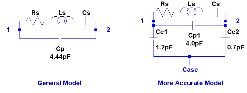
There is one more small detail yet. The crystal capacitance Cp is generally thought of as being across the crystal terminals. However part of the capacitance is to the crystal case as shown below when measuring the crystal as a 3 terminal device. This does make a small difference if the crystal case is grounded which is usually done for better stopband attenuation. From the schematics below 4.44pF(Cp) = Cp1 in parallel with Cc1 & Cc2 in series. Generally ignoring this small change has no detremental effect on the filter performance. Nevertheless LTSpice is happy to model the circuit either way and you can make your own decision.
There is one more small detail yet. The crystal capacitance Cp is generally thought of as being across the crystal terminals. However part of the capacitance is to the crystal case as shown below when measuring the crystal as a 3 terminal device. This does make a small difference if the crystal case is grounded which is usually done for better stopband attenuation. From the schematics below 4.44pF(Cp) = Cp1 in parallel with Cc1 & Cc2 in series. Generally ignoring this small change has no detremental effect on the filter performance. Nevertheless LTSpice is happy to model the circuit either way and you can make your own decision.
Click on picture for higher resolution image
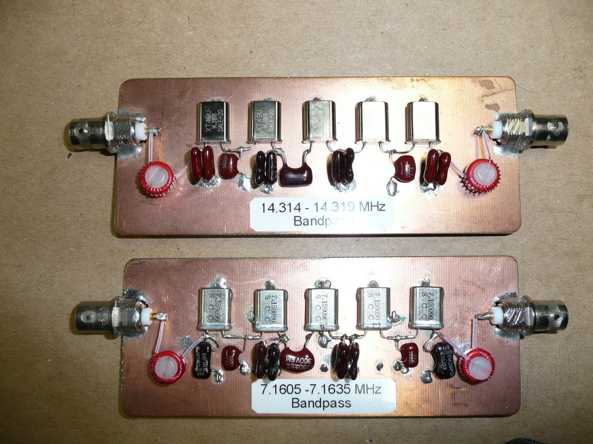
Both a 20m and 40m 5 crystal bandpass filter can be seen to the right. They are built on a piece of copper clad circuit board. The crystal cases are all connected to ground and the inductors are wound on T37-2 (u=10) cores with #28 enamel wire. All connections to ground are soldered directly to the copper and the connections between the crystals are held above the copper by the strength of the short leads. The capacitors were selected and matched to be within 1% of the design values and the inductors were measured @ 14.318MHz since the permeability of powdered iron changes slightly with frequency. The results can be seen below.
Nice flat passband with low insertion loss and BW = 5.5kHz
Wider sweep showing good stopband
SWR from either end <1.36:1 in passband
Results
I have been quite pleased with the results when building crystal filters using these steps. The measured response for this filter compared extremely closely with the simulated response for responses less than 85dB below the passband.
The crystal filters can handle +20dBm signals in both the pass and stop bands.
20m 5 pole crystal filter specs:
Passband: 14.314 - 14.319 MHz (~1.7dB insertion loss) SWR < 1.5:1
Stopband: more than -90dB for f < 14.285 MHz & f > 14.334 MHz
40m 5 pole crystal filter specs:
Passband: 7.160 - 7.163 MHz (~1.7dB insertion loss) SWR < 1.5:1
Stopband: more than -85dB for f < 7.125 MHz & f > 7.168MHz