Can High Impedances Be Measured Easily Throughout the HF Spectrum?
Measuring High Impedances With VNA
I often need to wind common mode chokes for EMI/RFI suppression. Data from tables and books can be used as guidlines but the actual impedances are never known for sure. The proliferation of inexpensive 1 and 2 port Vector Network Analyzers (VNA) in the past few years make RF impedance measurements easy. However common mode chokes are often designed for impedances greater than 1k ohms and the accuracy of these measurements is often questioned. These impedances represent VSWRs greater than 20:1 and often 100:1 for an instrument that is designed to measure impedances closer to 50 ohms. How accurate might the answer actually be? I will try to determine how easily and accurately an impedance of 10k ohms can be measured throughout the HF range. This value was chosen since very few common mode chokes exceed this impedance except at resonance. This problem is more than getting a 10K ohm resistor and measuring it in a small VNA. What if the measurement is not close to 10k ohms? Is the error due to the VNA, the test setup, or maybe the resistor under test?
Jeroen Belleman who works for CERN published a web page showing measurments of several 1206 size SMD resistors at RF frequencies. The website is http://jeroen.web.cern.ch/jeroen/resistor/shuntC.html and the figure below is from his web page. He concluded that all 1206 resistors had approximately 0.05pF shunt capacitance which obviously has more effect on the value for higher resistances. The tests were simple S21 measurements in a 50 ohm source and load environment where 0 ohms under test should be 0dB and 10k ohms should be -40.1dB and the figure agrees well at the lower frequencies. The increase in S21 at higher frequencies is due to the shunt capacitance. Note that small resistance values are more affected by the small series inductance as shown for values of less than 100 ohms.
Jeroen Belleman who works for CERN published a web page showing measurments of several 1206 size SMD resistors at RF frequencies. The website is http://jeroen.web.cern.ch/jeroen/resistor/shuntC.html and the figure below is from his web page. He concluded that all 1206 resistors had approximately 0.05pF shunt capacitance which obviously has more effect on the value for higher resistances. The tests were simple S21 measurements in a 50 ohm source and load environment where 0 ohms under test should be 0dB and 10k ohms should be -40.1dB and the figure agrees well at the lower frequencies. The increase in S21 at higher frequencies is due to the shunt capacitance. Note that small resistance values are more affected by the small series inductance as shown for values of less than 100 ohms.

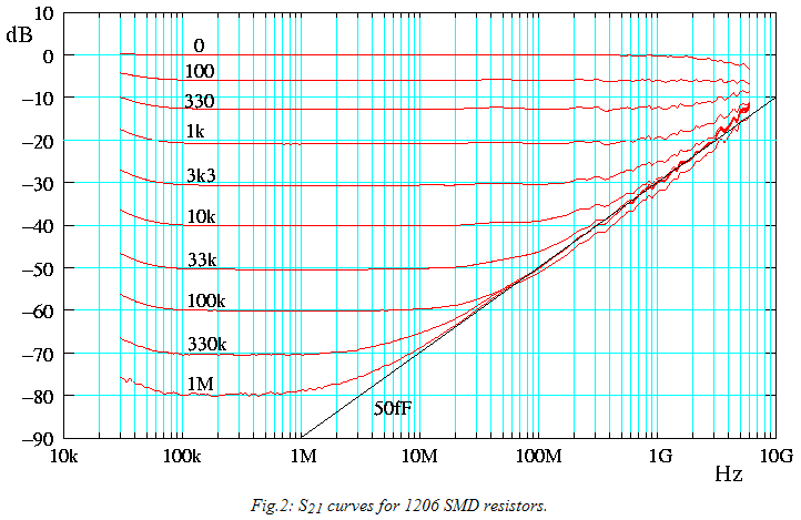
Figure above copied by permission of Jeroen Belleman, Aug. 23, 2011
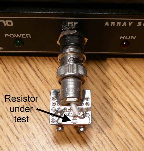
I decided to do the same test as Jeroen to see how close our results might be using my HP8753B VNA after careful calibration. The picture below shows the test fixture and the graph shows S21 for my 10k +/- 0.1% 1206 SMD resistor.
Test fixture
1/4W axial resistors shown
for size comparison
1/4W axial resistors shown
for size comparison
I calculated a shunt capacitance of 0.044pF @ 500MHz, 0.05pF @ 200MHz, and 0.06pF @ 100MHz using the increase in S21 at these frequencies. My results for the shunt capacitance are very close to those that Jeroen measured. Now I had a component that was very close to 10k ohms in parallel with ~0.05pF to measure with a small VNA. I used my AIM4170 and meticulously calibrated it in a very small fixture to see how close I could measure to the expected value.
Measured S21 with my setup
The fixture shown on the right is usable for both small leaded components via the little screw terminals and for SMD parts on the other side. I have used it to measure crystals and other small transformers. The SMD part under test is held down to the test fixture by a pair of ceramic tweezers with a rubber band to apply the pressure.
Prior to making measurements the fixture was calibrated "out" so that the reference plane was at the same location where the resistor under test would be placed. Careful calibration is extremely important to get the best accuracy from the VNA.
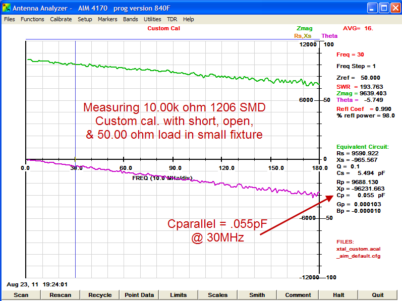
The resulting data (not shown) was ~9500 ohms in parallel with 0.055pF @ 30MHz. I thought this was quite good but gave Bob Clunn, W5BIG (creator of the AIM4170) a phone call to chat about accuracy of the instrument and the software algorithm). He suggested that I do a custom calibration of the 4170 which does a parabolic fit of the cal. constants and should be slightly more accurate. The data shown below is for a custom calibration and the impedance is now slightly better at ~9700 ohms in parallel with 0.055pF @ 30MHz.
Prior to making measurements the fixture was calibrated "out" so that the reference plane was at the same location where the resistor under test would be placed. Careful calibration is extremely important to get the best accuracy from the VNA.
The resulting data (not shown) was ~9500 ohms in parallel with 0.055pF @ 30MHz. I thought this was quite good but gave Bob Clunn, W5BIG (creator of the AIM4170) a phone call to chat about accuracy of the instrument and the software algorithm). He suggested that I do a custom calibration of the 4170 which does a parabolic fit of the cal. constants and should be slightly more accurate. The data shown below is for a custom calibration and the impedance is now slightly better at ~9700 ohms in parallel with 0.055pF @ 30MHz.
Bob also suggested that I do the open, short, load, calibration with a resistance higher than 50 ohms. The calibration algorithm in the AIM 4170 allows resistors other than 50 ohms to be used. Having the 3rd calibration point near the right hand side of the Smith Chart (where we expect the value of the measured impedance is) will somewhat minimize the error in this area but would slightly increase the error for low impedances. I used a 1.00k ohm 0805 0.1% resistor for the calibration and the following graph now shows the measured impedance to be an amazingly close 10.04k ohms in parallel with 0.05pF.
Page content last updated Aug. 24, 2011
Copyright © 2011 Larry Benko, W0QE
These tests were done for resistive and not reactive impedances but brief tests done on a 1pF capacitor (-j5300) @ 30 MHZ and then with the 10k resistor in series with the 1pF capacitor (10K-j5300) showed similar accuracy to the resistive load.
Generally common mode chokes having common mode impedances in excess of 1k ohms will be physically much larger than a 1206 size SMD resistor. How much will our measurements be compromized if small leads are used to connect to the component being measured?

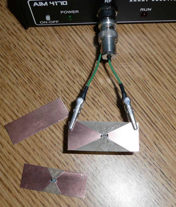
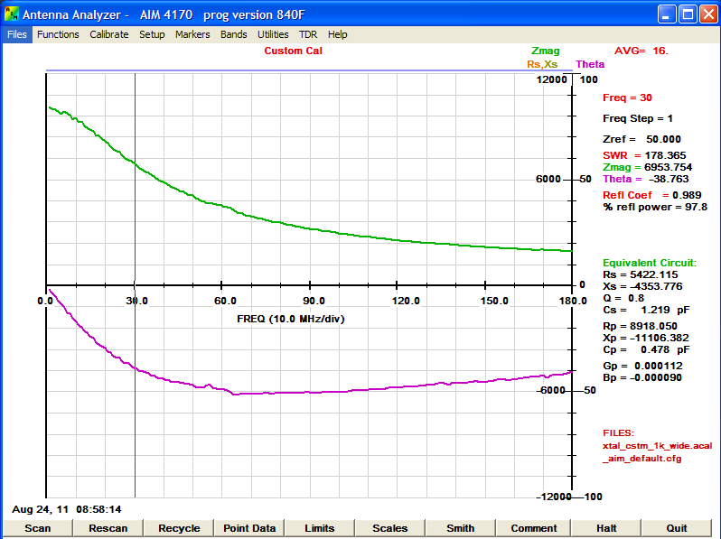
The picture and graph to the right show short leads which were calibrated via small pieces of circuit board approximately in the position used to measure the component. Calibrations were done with 50 ohms and 1k ohms but all efforts to reduce the stray capacitance below about 0.5pF were not successful. Nevertheless, the resulting data is still fairly accurate and useful with about a 30% error in the magnitude of the impedance @ 30MHz and a 15% error at 15MHz.
I believe this error is due to the calibration and in particular the "open" standard used for calibration. Doing the same measurement with my HP 8753B produces errors that are similar to the AIM4170 when calibrated with a 50 ohm resistor.
The circuit board to the right with the 10k ohm 1206 resistor measures -40.3dB @ 7.1deg. phase angle in a S21 test on a 2 port VNA where the 2 ports were calibrated and then separated 2 inches on a copper sheet with the circuit board connected. The circuit board was at right angles to the copper ground to minimize capacitance. This S21 measurement when converted back to impedance is approximately 10,300 ohms in parallel with .065pF which is much more accurate than the single port S11 measurement.
Conclusion
The accuracy of single port VNA measurements in the 1k ohm impedance range is quite good and is acceptable in the 10k ohm range if care is taken when making the measurements. Use the shortest leads possible, calibrate to the ends of the leads with components that are very accurate, and average the readings. After all, we are trying to make a measurement of a terrible VSWR fairly accurately.
I suspect that other small VNAs which allow for moving the reference plane to the location of the device being measured will be capable of similar measurements if carefully calibrated.
I suspect that other small VNAs which allow for moving the reference plane to the location of the device being measured will be capable of similar measurements if carefully calibrated.